Options for pulse compression for 2p imaging

This topic came up on social media and I’ll jot a few notes here in case it might be useful for others.
I posted about this a year ago, but it was about when you need a prechirper. I’ll elaborate on what kind here.
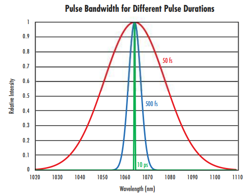
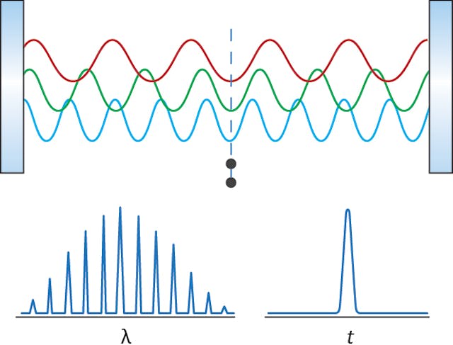
Ultrafast pulses of light are essential for multiphoton excitation (2p,3p) in imaging and optogenetic activation. These pulses are very short, around 100 fs, and thus they are made up of a bunch of different wavelengths. A laser pointer is CW — “continuous wave” — and it is nearly (not perfectly) a single wavelength. Laser used in confocal imaging are CW too. But pulsed lasers have different wavelengths of light [1], maybe +/- 10 nm around 910 nm, or +/- 50 nm around 1300 nm.

Since there are multiple wavelengths in the pulses, then we need to get all of those wavelengths to the same place at the same time. This is complicated because shorter wavelengths (higher frequency) of light travel slower through glass than longer wavelengths. The index of refraction for a glass is a function of wavelength of light. Take the speed of light in a vacuum (3 x 10^8 m/s) divided by the index of refraction to get the speed of light in the glass. In the plot below, you can see that typically index rises fastest towards the shorter wavelengths, but there is still a significant slope in the near infrared (IR) wavelengths that we use for multiphoton imaging and optogentics.

So our nice short pulses get blurred out in time. The longer wavelengths come out first and then the shorter wavelengths. These longer pulses are less effective at driving two-photon excitation.
What’s the solution? Well, we use a “pre-chirper” or a pulse compression device to impart the opposite effect ahead of time, then as the pulse transits through the glass, it’s nice at short (“transform limited” — in that it’s the shortest possible pulse in time based on a Fourier transform of the bandwidth) at the plane of focus [2]. To do that, we need to find a way to get the shorter wavelengths ahead of the longer wavelengths. That is done in our pre-chirper, which makes the path length for short wavelengths longer than the path length for longer wavelengths– exactly the opposite of what happens in the glass. There are several ways to do this.
Prisms
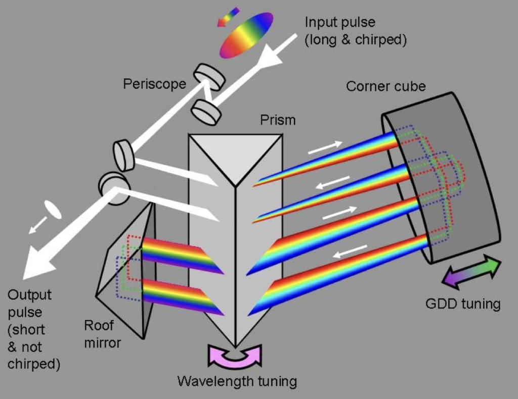
One way is with a prism. And I’m going to direct you to this resource at Swamp Optics. Rick Trebino’s web site is beautifully done. The illustrations and writing are crystal clear and accessible. Here is his tutorial on pulse compression which also explains why his single prism layout is nice. I agree with him, and every prism-based compressor built in my lab has used this design idea with a single prism and 4 passes (using a roof mirror, a corner cube reflector, and a sharp edge mirror). It’s patented, so if you want a turnkey one, you have to buy from him. The other one-box pulse compressors use a different design. They can be convenient solutions.

[added 30 Apr 2024]: On a twitter discussion, Chi Liu kindly reminded me of this work by Lingjie Kong and Meng Cui. It is very similar, but uses a roof mirror instead of a corner cube to reflect the beam. It changes the geometry a bit, but still works. The idea is that this will decrease the polarization changes that can occur with corner cube reflectors. Polarization changes are a problem because you want to use p-polarized light and hit the prism at the Brewster’s angle, where p-polarized light is transmitted 100%. If the polarization is rotated a bit and there’s a non-zero s-polarization component, then part of that light is lost as a surface reflection. And most antireflective coatings don’t work at that angle of incidence. We use uncoated prisms. By the way, this aspect of prism compressors– that the beam is always approaching at Brewster’s angle– is part of the reason why we use custom prisms for a particular wavelength. The apex angle of the prism needs to be just right for maximum throughput at a specific wavelength (Brewster’s angle is a function of the index of refraction, which is a function of the wavelength of light, as seen above). Nearby wavelengths can still work, but overall throughput will be lower. We usually just set it and stay on the same wavelength. When we’ve had two different wavelengths (e.g., 910 nm and 1040 nm) we have two completely different prism compressor setups.
Polarization changes, and strategies to mitigate them including using this variation, are discussed in Trebino’s patent:
According to the present invention, the corner cube 120 leaves the polarization of the input beam (pulse) of light intact. The periscope 130 used at the output changes only the beam height and thus does not affect the polarization of the input beam of light either. However, the last mirror 175 used to make the output beam of light 165 collinear to the input beam of light 140 could, in principle, rotate the polarization slightly. This can be avoided by selecting the last mirror 175 having a highly reflective surface as the first mirror 171 has. This simply requires a highly reflective coating on one surface and an anti-reflective one on the other of the mirror. Hence, this mirror becomes an effectively “infinitesimally” thin mirror. This way, the pulse compressor 100 yields the output beam of light having the same polarization as the input beam of light 140. AR-coated beam- steering compensator plates 172 and 174 could then be used to restore input-beam and output-beam collinearity. According to one embodiment of the present invention, the polarization rotation caused by the pulse compressor 100 was measured to be less than 0.31 degrees.
Alternatively, a beam periscope may be placed before the first optical path through the prism for yielding zero polarization rotation. Referring to FIG. 6, a pulse compressor 600 according to another embodiment of the present invention is shown. In this embodiment, the pulse compressor 600 has a beam periscope 645 adapted for receiving an input beam of light 640 emitted from a source of light and directing it towards a mirror 671. Once the mirror 671 receives the beam of light, it reflects it along a first optical path 651 towards the prism 610. Such an arrangement of the beam periscope 645 ensures no polarization rotation of the input beam of light 640 to be yielded. Additionally, according to this embodiment, a roof mirror 630 is utilized for for receiving a beam of light along an incident optical path and returning it to form a returned beam of light along an output optical path that is anti-parallel to the incident optical path, wherein the beam of light and the returned beam of light have the same spatial order of colors.
Chirped mirrors
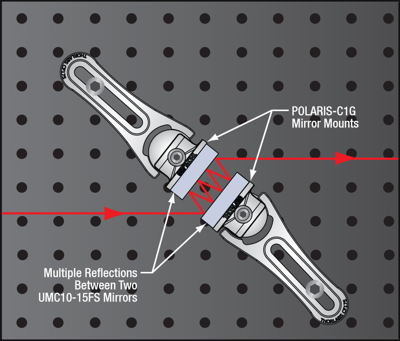
In addition to prism based compressors, chirped mirrors are another option. These use mirrors with reflective coatings that reflect longer wavelengths more superficially and shorter wavelengths deeper into the surface. In this case, each reflection does a bit of compensation, and you bounce your laser off of a mirror pair (or a series of pairs) until you get the amount of compensation you want. It’s simpler to align, but less flexible.


Thank you for this overview! We just had a discussion about this in the lab.
Beyond 850 nm, the built-in dispersion compensation of turnkey Ti:S laser systems tends to be insufficient to compensate for the dispersion of a typical 2P microscope with Pockels cell (I can confirm this for our res-galvo-galvo 2P microscope with Coherent Chameleon Vision S: the dispersion is around ~18-20k fs^2, but the laser system’s compensation range @ 920 nm ends around -12k fs^2. The MaiTai DeepSee seems to have a similar limit).
The simplicity of chirped mirrors is really appealing, but at 920 nm they only compensate by ~-140fs^2 per reflection and ~50 reflections just seemed a lot to me. External, Trebino-type prism-based approaches are very effective, and we use them in our lab, but I found wavelength tuning quite inconvenient. In practice, this addition turned our Ti:S laser into a single-wavelength or tune-only-if-you-really-really-must source.
The most common simpler alternative for galvo-only setups is to simply get rid of the Pockels cell, modulate power (slowly) with a motirized waveplate-polariser combination and accept the added photodamage during laser flyback. On resonant scanning setups, however, bleaching at the edges can be considerable and some form of fast modulation seems necessary.
I consider this (a resonant 2P setup) to be the clearest use case for a fixed-wavelength fiber-based fs-pulse laser source. Their dispersion compensation tends to have a much larger range at 920 nm (up to 40k fs^2), more than enough – especially if you buy them with built-in optional AOM power modulation, which makes Pockels cells obsolete (lowering the required compensation to < 10k fs^2).
Good points. We don’t use Pockels cells on our rigs. There can be cms of KD*P in those, and thus can be a major source of dispersion.
And we avoid tuning too. Like you said. In one set up, we had separate beam paths and prechirpers for the two commonly used wavelengths. That can work for more wavelengths too, but practically I wouldn’t want to scale it up to more than three if I didn’t have to.
We tested a chirped mirror unit from Coherent that went up to -69,000 fs^2 at 920nm using 36 bounces. We used it at -54,000 fs^2 and it worked pretty nicely. Nearly 90% throughput.
To avoid photodamage during laser turnaround (not flyback) for the resonant scanners, you can use a physical object to blank the scanned beam at the edges of the FOV (needs to be adjusted for different zoom levels). One such implementation is described here: https://www.researchgate.net/profile/Marcus-Leinweber/publication/260874911_Two-photon_Calcium_Imaging_in_Mice_Navigating_a_Virtual_Reality_Environment/links/5784d52708aee45b8444803e/Two-photon-Calcium-Imaging-in-Mice-Navigating-a-Virtual-Reality-Environment.pdf
Che-Hang Yu has done that in our lab too. Super simple.