EasyEDA update – online circuit design
Posted in Uncategorized
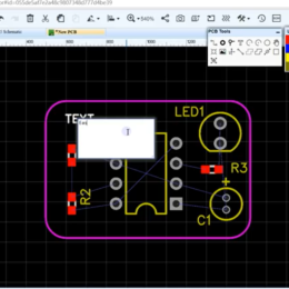
We posted about EasyEDA years ago. They’re going strong. They’ve updated the software, and added an online, free Gerber viewer. They’ve also branched out and sell components.
…
We posted about EasyEDA years ago. They’re going strong. They’ve updated the software, and added an online, free Gerber viewer. They’ve also branched out and sell components.
…
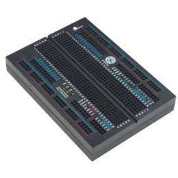
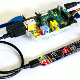
It’s a microcontroller built into a breadboard. Actually, TWO microcontrollers. Both are Arduino-compatible. ATmega16U2 and ATmega328P.
It comes in both black, white, and pink because style matters.
P.S. The bottom side is…
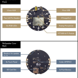
In an earlier post, we discussed how surprisingly useful well designed voice control can be. There are open source software solutions for voice control, but they aren’t integrated with hardware, and there wasn’t really a kit to help one get started. Now there is.
Here’s an open…
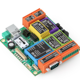
Tibbo makes modular microcontrollers, with plug-in modules for I/O ports (e.g. DB9), relays, sensors, digitizers, etc. They have different sizes, the largest of which is available as a Linux version.
…

Andrew Lim wrote in to discuss strategies on dealing with ripple noise in 2-photon imaging systems, particularly when using resonant scanners. He writes:
This isn’t so much a tip as a problem with resonant two-photon…
Sanworks has a whole series of devices for behavior experiments. Everything is open source and well documented. You can also pay them to assemble the devices if you choose.
…
“>
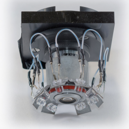
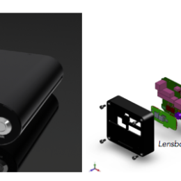
Leonardo Lupori and Raffaele Mazziotti are two fellows in lab of the excellent Tommaso Pizzorusso. They have developed an intrinsic signal optical imaging rig and are sharing all of the materials. Here’s their web…
It’s been promised for a while now, but someone has to do the hard work to make it happen. That inevitably involves some pretty pitiful looking stepping stones on the way to the…
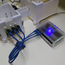
Austin Blanco has designed and built an open-source system for controlling complex imaging systems called TriggerScope. It’s highly customizable out of the box, and both the firmware and software are open.
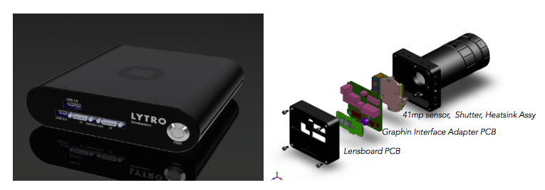
Lytro is releasing a development kit for their light field camera. That’s nice, but it pretty expensive. And we’ve been able to buy light field cameras for technical uses for years.
What’s…
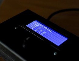
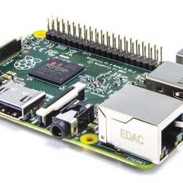
One can use a Raspberry Pi as a highly customizable 20 MHz scope with this cute little BitScope Micro. (about 120 euros, from the OE store)
They have …

MultiSIM BLUE is yet another free, SPICE-based electronics simulator– this one is linked into the MOUSER catalog, to streamline parts sourcing. Also includes PCB design tools.
…
ScanImage 5 supports resonant scanning with a wide range of hardware. So custom rigs can add resonant scanning pretty easily, while sticking with ScanImage for acquisition.
It takes about $10,000 worth of electronics…

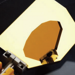
Our friend Christian Wilms tipped us to Austin Blanco’s blog, which has some posts you all might be interested in:
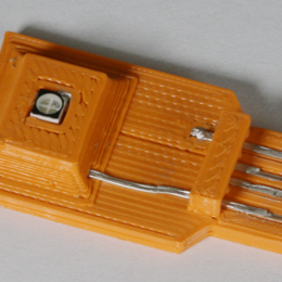
Characterizing unknown optical components
A few notes on Arduinos, their timers, and using…