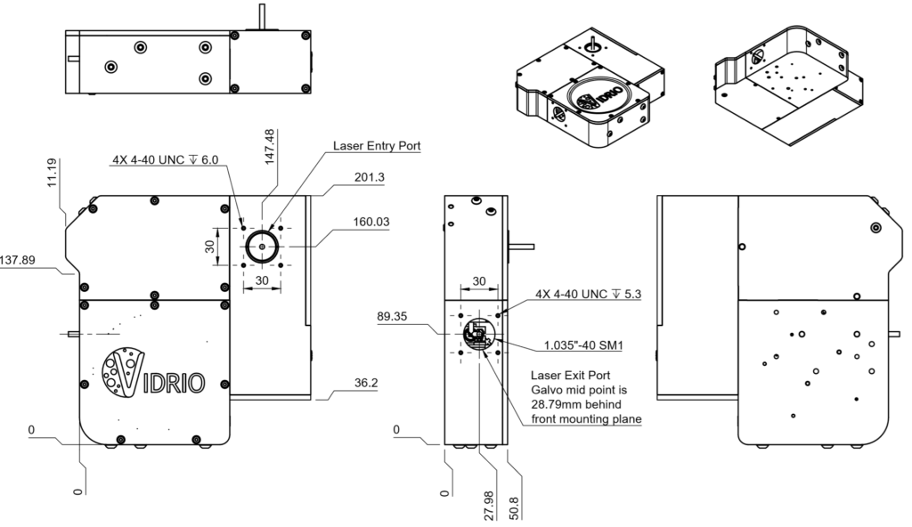
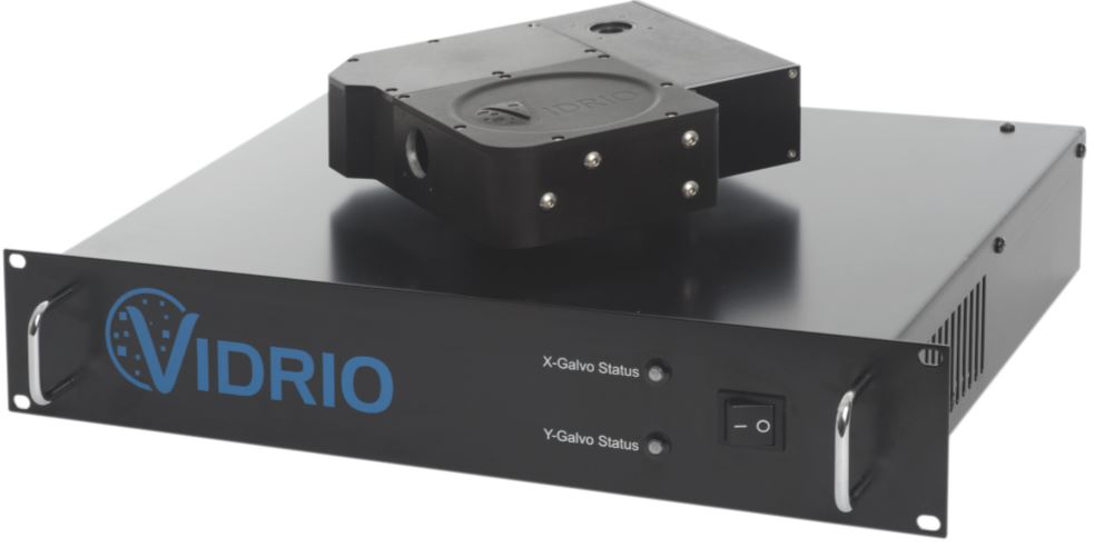
A resonant-galvo-galvo module from Vidrio/ScanImage
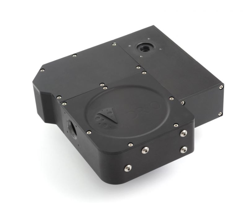
This could be handy for some of you. Resonant scanners are fast, but inflexible. You can’t tell them where to go. They just oscillate at a fixed frequency. All you can do is control the amplitude. You can’t even apply an offset– they always oscillate around the same central point. So you can’t pan around with a resonant axis. You have to move the optics or the specimen.
Here’s why that’s a problem: Consider the case where you have several small regions-of-interest within a larger field-of-view. You could scan the full field of view and then only analyze the ROIs you are interested in. However, you pay a price in frame rate because you’re spending a lot of time raster scanning areas that you’re not interested in. It’d be better to just raster scan a small region and then move that around in X and Y. The usual resonant scan systems won’t let you do that because you can’t pan along the resonant axis.

Resonant scanners are usually paired with a standard galvo for Y deflections (by convention, the fast axis is often called “X”, and the slower axis is “Y”). So the “dumb” resonant scanner just scans in X quickly, and the Y mirror defines how many scan lines per frame and is also used to pan in Y. If you want to pan in X, one solution is to add a third mirror. E.g., resonant X -> galvo X -> galvo Y.
Almost exactly 3 years ago, Vidrio asked me to write a letter in support of their NIH proposal to develop software and hardware for this approach. Here’s an excerpt of that letter:
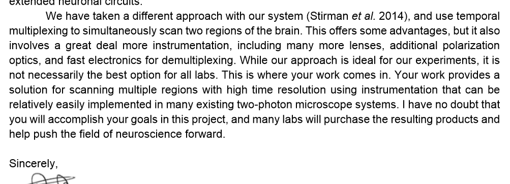
They got the funding. I doubt my letter had much to do with that. I just included the excerpt above because it clearly states why I think something like this is useful. Vidrio did the work, and they now sell a hardware module for multi-region resonant scanning that can be fitted into a Sutter MOM, a Thorlabs scope, or a custom scope. I’ve been chatting with Georg, Jonathan, and Bruce at Vidrio about the product.
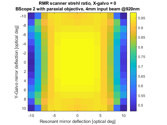
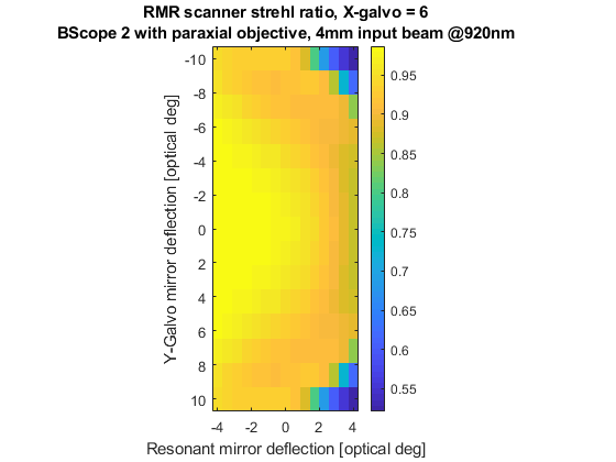
It looks like they did a good job. They provided plots of Strehl ratio (good = 1, bad = 0) as a function of mirror angle. Granted, these are nominal values, but it looks good enough that I would expect this system to work well.
Here’s the resonant axis:
Here’s what the Strehl ratio looks like along the resonant axis if the linear X galvo is offset 6 degrees:
Here are the figures for beam diameter and scan angle: 4 mm beam diameter at the input and output (i.e., no internal beam expansion), 20 degrees scan angle. So if you need to fill a 20 mm back aperture, you’ll need a 5x beam expansion, and the angle range will decrease to 4 degrees (+/- 2 degrees). That’s still pretty decent for most commercial objectives. The performance of the objective itself will probably be limiting around that range.
One implementation of this code and general scanning approach (albeit with different hardware) is Sofroniew et al. 2016.