Ripple noise on PMTs in 2-photon imaging

Andrew Lim wrote in to discuss strategies on dealing with ripple noise in 2-photon imaging systems, particularly when using resonant scanners. He writes:
This isn’t so much a tip as a problem with resonant two-photon scopes that several people have told me they also have but I haven’t seen a solution for (other people apparently just ignore it). I wonder if you could raise the issue on the blog to see if people have ideas, or if you know of a solution, maybe you could post it?
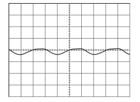
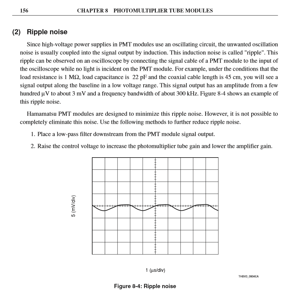
Apparently the GaAsP PMTs from Hamamatsu (like all PMTs) have a certain amount of ripple noise stemming from the high voltage power supply in the PMT, in the frequency range of 200-300 kHz. On a resonant two-photon, when the PMTs are on but not receiving any light, this shows up as oscillations in the signal on each line of the image, and because the frequency of the ripple noise doesn’t exactly match the time it takes to scan each line, these oscillations show up as diagonal patterns on the image. If the signal is bright enough, these patterns don’t really matter, but if you are trying to image something dim, the patterns can obscure the image.
One solution could be to remove the oscillations in post processing: since they are regular, one should be able to undo the Sanderson correction, detect the frequency/phase of the oscillation, and just subtract the ripple noise. But before embarking on this project, I wanted to find out if anyone else might have done this already, or have better ideas.
Hamamatsu shares this information on the ripple:

Jeff Stirman shares his thoughts on this:
I have noticed this ripple noise as well when imaging dim objects and it can be quite annoying. However, I never saw this when I was performing acquisition in photon counting mode. Also, more recently we have moved to somewhat of a hybrid analog photon counting mode and again I do not observe this. To clarify: I do not see this when my discriminator level is set to an amplitude that exceeds the ripple. For both photon counting and analog photon counting (see Moon et al, “Analog single-photon counter for high speed scanning microscopy”, Optics Express, 2008) a discriminator is used after the amplified PMT signal. The output from the discriminator can either by counted directly by a high speed counter, or can be digitized (analog integration). We do the latter because we did not find a counter of sufficient speed. (We are performing discrimination for demultiplexing purposes.) When the level of the discriminator is set higher than the level of this ripple noise, then it is effectively filtered out. Of course if your signal is on the same order as this ripple noise, then it too is filtered, but we always have signal > ripple so it is effectively filtered.
Another source of intermittent periodic noise in two-photon imaging can be an ultrafast laser that is not fully modelocked, although this noise usually manifests regardless of brightness . Trimming up the modelocking causes the noise to disappear. Sometimes switching the wavelength slightly, e.g. from 920 to 915 nm, can hit a modelocking sweet spot and get rid of these pesky artifacts if you’re in the middle of a crucial experiment. I find it useful to have a pickoff going to a laser spectrum analyzer (“Rees kit”) to keep an eye on the excitation source at all times. This problem can be particularly acute if one puts a Pockels cell too close to the laser head, resulting in back reflections into the laser cavity that interfere with modelocking.
What does that modelocking noise look like? I’ve seen complete signal black out when modelocking intermittently fails (CW breakthrough), but are you seeing more subtle noise?
Yes, be careful of back reflections into the laser. Those problems can look very strange. Don’t let stray laser light hit a thin wire either, it can cause electrical artifacts.
I remember seeing such modelocking artefacts many years ago with a Tsunami. The artefacts didn’t look like a CW breakthrough on the Rees Spectrum Analyzer (sharp peak on top of the Gaussian curve), but rather like the entire Gaussian curve was modulated with a high frequency sine wave. When this happened the images would show diagonal noise patterns quite similar to the ripple noise patterns described above. The patterns would appear suddenly, and the first time I saw them I was quite puzzled. But as Adam said, you could easily get rid of these modelocking artefacts by tuning the wavelength up or down a bit and then bring it back to the desired wavelength. It didn’t happen very frequently and was so easy to rectify that I never looked into why this happens.
In my hands (Mai Tai lasers), the modelocking noise shows as a modulation of the peak intensity, with a rather stable modulation periodicity of few microseconds. This shows then as diagonal stripes in the picture fore resonant scanner, and does not show at all for non-resonant scanning.
For detection of this issue, you can hook an oscilloscope to the 80 MHz sync output of the laser (which is basically a fast photodiode), then you will easily see the amplitude modulation. By lowering the pumping power of the laser to a lower level, you can reproducibly generate this modelocking noise. You can often circumvent the problem by going to a slightly different wavelength or by increasing the pumping power, or by having your laser engineer re-align the mirrors of the caser cavities.
All of this applies to Spectra physics lasers; I do not remember whether it is possible to manually adjust pumping power for Coeherent lasers.
To my experience, backreflections into the laser do not generate mode-locking modulational noise, but simply shut down mode-locking completely for some seconds.
Here’s an example of oscilloscope screenshots, from 910 nm to 940 nm of a not well-behaving laser. The picture title indicates the wavelength, and the effect (modulation) only shows for some of the wavelengths of the sweep: https://www.dropbox.com/sh/1ivk7x500iw0iss/AAAtBdAumnyPEWJ90lUJoAeTa?dl=0
[…] The recent post on ripple noise generated some comments and additional discussion. Go check out the comments on that post. For example, Peter Rupprecht shared some snapshots an oscilloscope display showing the signal from the BNC connector at the back of the laser, in the presence of this ripple noise. The ripple is seen when the laser is tuned to some wavelengths but not others. […]
After a bunch of mails back and forth w/ our PMT vendor & reseller I decided that there is not much we can do about the PMT ripple noise of our H7422s in terms of analog filtering and digital post processing.
Therefore I’d like to implement Jeff’s ‘analog photon counting’ on our setups. This sounds like an extremely easy SNR-boosting add-on requiring minimal hardware changes.
I have a few questions, though (Jeff?):
You guys chose to go with the high BW 1.5Ghz Hamamatsu C5594 pre-amp but then used the (sadly discontinued) 150MHz 4608C LeCroy discriminator. I could be wrong – but Isn’t that massively ‘over-censoring’ the photon count (i.e. wouldn’t you want to go much higher cont rate to not lose events?)?
Without wanting to experiment much w/ different hardware I thought of blatantly copying Xu et. al 2015 (http://www.ncbi.nlm.nih.gov/pubmed/25227160) and go with the 400MHz Femto HCA-400M-5K-C pre-amp and our local FAST ComTec TD2000 GHz Discriminator (set to 1-2ns output)…
I assume this makes sense, but where I am uncertain is the pre-DAC filter:
You have used a 4.5 MHz low-pass filter to integrate the NIM pulses from your discriminator and fed the signal to your 25MHz Alazar card. In our case we use the 125MHz Alazar ATS9440 locked to the 80MHz pulse rate of our laser. What filter would you suggest in this case? I assumed that going 60-80MHz LP would be appropriate (mimicking the bandwidth of our current Thorlabs pre-amp). Using the same DAC-rate to filter ratio from your setup, however would rather mean 15MHz LP…
Thanks for your help!
T
(This reply was written by J. Stirman.)
Yes, this is a great way to reduce ripple noise and homogenize the output of the PMT. On the current Trepan2p scope we use the 150MHz discriminator. And yes it is possible that we lose some of the fast signal. But given the probability of photon generation per pulse, it is unlikely. Furthermore, we have and will use the TD2000 in future implementations, and as you know these are ridiculously fast. In comparing using this and the LeCroy, I saw no difference (making me think we are not losing signal using the slower discriminator). But for sure, use the faster TD2000.
Great idea to copy the Wu et al work. We will basically do that as well. We will use the veto input to the TD2000 for our multiplexing in the next generation scope.
We have several passive filters on hand from TL (https://www.thorlabs.com/newgrouppage9.cfm?objectgroup_id=8613) and we choose our filter based on our sampling rate (and hence number of pixels). We actually use the ATS860 (http://www.alazartech.com/product/ats860) which is really fast. We have the upgrade for synchronization as well. After the discriminator, you can still sync to the laser and not use a low-pass filter… right? I do not see why not. If you want to sample very fast then you must sync to the laser to avoid anti-aliasing effects as discussed elsewhere (https://scanbox.wordpress.com/2014/03/18/synchronize-to-the-laser/). In my hands I have not seen the need to sample this fast. I have synced to the laser and in my hands this made the image ‘worse’. I really think this is due to an overall decrease in the signal strength. Under conditions of strong signal, syncing to the laser should increase S:N but might decrease the overall signal. I’m not sure about this. Also, I do not like to sample this fast because that is A LOT of data to store that we eventually collapse to a single 1D vector neuron trace. But that’s just my opinion :slightly_smiling_face:
Regardless I think you can still sync to the laser post TD2000. OR, use a low-pass filter that is suitable for the sampling frequency. The sampling frequency should be 2x or more of the filter cutoff. There are many resources online discussing the filter freq versus the sampling freq. For most of our work we use a 1MHz filter and a 5MHz sampling rate. For an increase in the number of pixels, we sample faster and choose a filter with a higher cut-off freq. What I would love would be a variable rate filter so I could fine tune the filter to match the sampling rate. Also I have seen some issues with the type of filter from Thorlabs. They are high-order elliptic filters and this can lead to some ringing artifacts. I only see this in bright areas. From reading it might be better to use a Butterworth filter. So what I really would want would be a variable rate filter with the ability to choose between many different types and then I could really fine tune the system.
In the end, I would choose the sampling rate you want based on your dwell time, number of pixels, etc., and then pick a low-pass filter that is ~5 times lower than that. That is a super super rough guideline. I think empirically testing is a better approach.