Ripple noise on PMTs in 2-photon imaging – Part 2
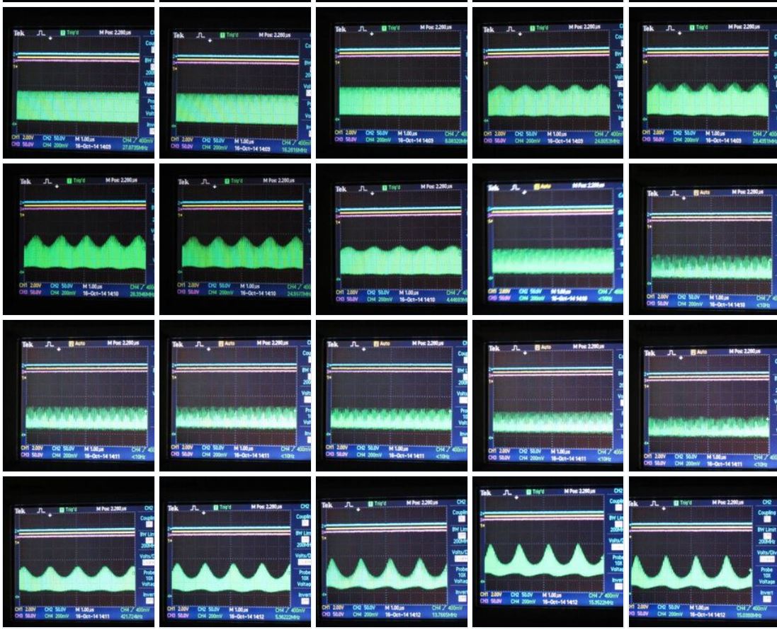
The recent post on ripple noise generated some comments and additional discussion. Go check out the comments on that post. For example, Peter Rupprecht shared some snapshots an oscilloscope display showing the signal from the BNC connector at the back of the laser, in the presence of this ripple noise. The ripple is seen when the laser is tuned to some wavelengths but not others.
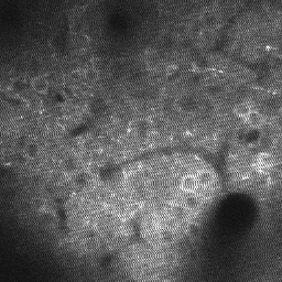
Adam Packer kindly shared some of his data so we can see what it looks like. You can see the high frequency noise in single frames (an example is at the top of this post) and the video (below).
In vivo data from an awake behaving animal injected with GCaMP5 in somatosensory cortex, imaged at 920 nm with approximately 50 mW on sample using a GaAsP PMT (control voltage set to ~600) on a Prairie Ultima microscope (3.6 us dwell time, 4x optical zoom, Nikon 16X 0.8 NA objective). The ‘wavy’ noise disappeared after the Pockels cell was moved further away from the laser output, reducing the incidence of back reflections into the laser cavity. This data was recorded on September 7th, 2012.
Darryl McCoy (Product Manager Chameleon and Fidelity Ultrafast lasers at Coherent Inc.) wrote in and shared the perspective from the laser side. This information can help in troubleshooting, so I’ve pasted a
We usually try initially to get a view of frequency of the ripple (harmonics not withstanding) to get an idea of whether the effect is high frequency ie >1 kHz, variable – ie appears to change with wavelength or other factors, or low frequency.
High frequency, regular patterns as you have mentioned often seem to be down to detector issues or perhaps alignment. Often we go around a circle where customers are so exhausted in finding the source that they insist to change to laser, or even laser type. It rarely solves the issue.
When things come and go, and the frequency changes it gets really tricky. Adam, you right on the money with the modelocking, especially CW breakthough. To truly see it in the subtle form that can cause this you need a higher resolution spectrometer than a standard Ocean optics device. A Rees system works – but these are hard to find these days. In the factory these days we use the APE Wavescan for the new build stations. We continue to scour the world for a more cost effective and portable solution!
Usually CW breakthrough occurs when pumping too hard. A one off, single wavelength correction to the pump laser setting is possible – and could be done remotely. Doing this blind does come with some risk as you may fall off the “other side” – not enough pump power will lead to qswitching. This is actually more likely to cause kHz noise than CW breakthrough. There is an optimum window, which we simply term the modelocking window. It gets smaller on the edges of the tuning range, especially for shorter pulses. So in general we recommend that a service engineer is called in to properly calibrate and optimise across the tuning range. We have seen this process fix ripple noise.
There are other causes of intermittent and variable ripple noise, eg bad air circular pumps, environmental issues and pockels cell issues such as back reflections and thermal blooming. If you have loads of power in hand, then sometimes DKDP can benefit from reducing laser power by half with a wave plate/cube combination before the PC.
In the case of Chameleon TiSa lasers, we occasionally see noise at 25Hz if the scan setup just happens to be of a frequency to show it, and the SNR is low. This can be caused by the internal automated feedback loops running in the laser for pump and cavity alignment. Both can be disabled, usually with no ill effects other than some longer term drift. Other laser manufactures will likely use something similar though perhaps at a different frequency.
Thanks, Adam, Peter, and Darryl. We really appreciate you sharing this information.