More MATLAB code for 2p scope design

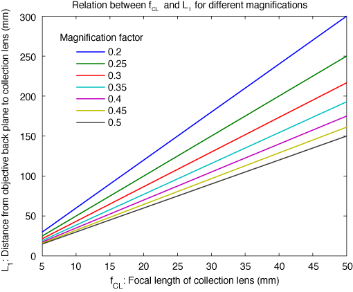
In the last post, I mentioned how the “minification” factor (the diameter of the PMT detector divided by the diameter or the back plane of the objective), greatly affects the layout of the collection optics. Here’s a graph and the associated MATLAB code for looking at this relationship. If you need to fit two dichroics in the collection pathway (IR/vis and red/green, for example) then you’ll need a larger distance between the objective and the collection lens.
Also consider the diameter of the objective’s back plane. If it is one of the large NA, low mag objectives, it will be quite large and you’ll want to use at least a 25mm collection lens, if not larger. By contrast, if you’re using a 40x/0.8 objective, you can probably get away with smaller lenses and closer positioning.
%% Magnification, dist_obj_cl, f_cl
% Eqn. 3.21 from Tsai et al. 2009 (CRC); abs(mag)=f_cl/(dist_obj_cl-f_cl)
% Can be rewritten dist_obj_cl = (f_cl/mag) + f_cl
% Below, for brevity, we use L1 = dist_obj_cl

clear f_cl L1
% Make a family of curves relating these quantities.
f_cl = 5:5:50; % Collection lens focal lengths, in mm.
mag = 0.2:0.05:0.5; % Magnification factors.

for m=1:numel(mag)
    for f=1:numel(f_cl)
        L1(f,m) = (f_cl(f)/mag(m)) + f_cl(f);
    end
end

for m=1:numel(mag)
    M{m}=num2str(mag(m)); % Labels for the different mag lines
end
figure
plot(f_cl,L1);
xlabel('f_C_L: Focal length of collection lens (mm)')
ylabel('L_1: Distance from objective back plane to collection lens (mm)')
legend(M,'Location','NorthWest')
legend('boxoff')
title('Relation between f_C_L and L_1 for different magnifications')