PMT power supply
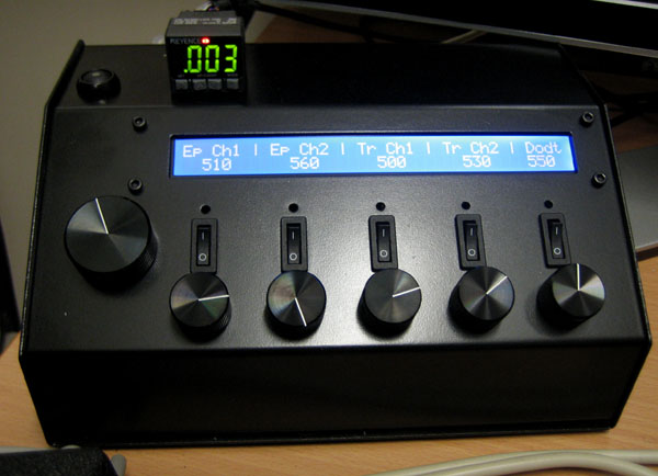
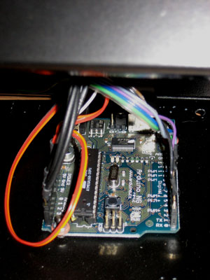
I was cleaning house a bit, and among my old files I found this, which might be worth sharing. Years ago I made a centralized power supply for a custom 2-photon imaging system I built. There were two epi detectors (for red & green fluorescence) and three trans detectors (red, green, and IR-based “DIC-like Dodt” contrast). I had an Arduino control everything. There were knobs for setting PMT voltages, and switches for turning individual channels on-and-off, and a master for switching everything off when opening the light-proof box. The big knob to the left controlled the laser intensity (it was hooked up to a stepper that turned a half-wave plate to split off some of the power using a polarizing beam splitting cube). The Arduino controlled the LCD display too, reading in analog signals and converting them to actual voltages for display.
The green display on top is a pressure sensor, which we used for patching.
Design and programming was very fast and easy. The machine shop modified the instrument box to my specs, and painted it for me. What took the longest was soldering everything up. That alone took most of an entire day.
It worked fine, and it was nice to have a tactile interface.
In my own lab, I took a different approach. I use Processing to talk to Arduinos and I have a simple GUI to adjust the PMTs. Less soldering, but no tactile interface (unless you count clicking the computer mouse). It works mostly fine, but when rebooting the host computer, the USB port assignments sometimes change, and it takes changing the Processing source code to get it working again. In practice, it only comes up once or twice a year, so it’s not a big hassle.
What power supply do you use that an arduino can talk to?
I used something from AMS Technologies, part of their “HV Rack” line. But I can’t find it online right now. Maybe they stopped making them. They had a custom interface for controlling the supplies that was very simple. For example, there was an analog input for setting voltage/current on one channel, a digital output for reporting whether a channel was on, etc. So there were a ton of pins on the connector, but the interface was very simple.
More recently, I’ve been using Arduinos to talk to Hamamatsu’s M9011/M9012 control boards. I’m not sure if they still sell those. I didn’t find them on their web site. I can send you a PDF of the manual if you’re interested.
For more general applications, I’d probably use one of these:
http://www.keysight.com/en/pc-856757/single-and-multiple-output-dc-power-supplies-for-basic-benchtop-and-system-applications?nid=-35673.0.00&cc=US&lc=eng
Those power supplies have GPIB, RS-232, and other interfaces. People have made GPIB adaptors for Arduino, but I’d probably try RS-232 first because that way seems more straightforward.
About the Hamamatsu M9011 and M9012… I just received an email that those products have been redesigned and have new names. They’re now M13413 and M13414. I still didn’t manage to find a link online. They sent a couple of PDFs in the email, but for complete information, we should probably just ask Hamamatsu for more info.